Cooling the Rotax 912 Voltage Regulator/Rectifier
 |
| Cooling shroud and black blast tube for voltage regulator |
We first became aware of potential overheating of components by the Rotax Minute - Component Temperatures video available for subscribers of rotax-owner.com.
The video mentions a temperature limit of 176 deg F, or 80 deg C, specified by Rotax for both voltage regulator and ignition module.
In our plane, ram air entering the cowl cools the ignition module.
Since that module does not generate any significant heat, and since air temperatures inside the cowl are well below the 176 deg F limit, we are not concerned about that module.
A different matter is the voltage regulator. It produces significant heat, as is implied by its cooling fins. Thus, excessive temperature is a concern.
Temperature Measurement
Rotax supplies adhesive strips, part number 897-140, that are stuck onto modules for measuring max temperature. Discolored segments on the strip indicate the max value.
The testing method is appropriate when hot days are a rare event.
For us, the Texas summer produces plenty of opportunities for checking performance at max ambient temperature.
For the temperature measurements, we acquired the low-cost Bell 22-1-28001-8 in/out thermometer, available from number of vendors including Amazon.com.
 |
| Bell 22-1-28001-8 in/out thermometer |
The sensor was a bit wide to be wedged between the cooling fins of the voltage regulator, so we clipped its sides without detrimental effect.
 |
| Clipped sensor |
Evaluation of Original Installation
While taxiing in 95 deg F ambient air, the temperature of the voltage regulator climbed rapidly; after 5 min, the thermometer showed 145 deg F, corresponding to a rate of increase of 10 deg F/min.
In fact, the rate showed no sign of slowing, so we decided to stop the taxi test and took to the air.
Ambient 85 deg F air at 2,500 ft MSL cooled the voltage regulator at a snails pace.
After 10 min of flight, the temperature had been reduced to 120 deg F and seemed to hold steady.
Evaluation
The test indicated that our main concern should be prolonged ground operation.
Given the 10 deg F/min rate of temperature increase computed above, the temperature of the voltage regulator during, say, 10 min of taxiing may rise significantly above the allowed max value of 176 deg F.
During the past 19 years, we have not seen detrimental effects, except for replacement of the voltage regulator after 1,330 hrs.
This is likely due to our flying pattern during summer trips: We prefer stops at uncontrolled airports, the first refueling stop generally is in late morning, and in hot weather we typically stop for the day in early afternoon due to strong turbulence or threatening weather.
As a result, taxiing usually does not require much time and is mostly done in comparatively cool air.
Cooling Shroud for Voltage Regulator
Van's Aircraft offers a neat cooling system for the Rotax 912/914 voltage regulator.
The key component is a cooling shroud, part number F-00002. It is riveted to the voltage regulator.
 |
| Cooling shroud |
Essentially, a 5/8" blast tube delivers cooling air from the engine cooling shroud to the voltage regulator cooling shroud.
Unfortunately, our Rotax 912 engine was delivered without engine cooling shroud, and we have never added one. So a different source for the cooling air had to be found.
Wrong Choice: Ram Air for Cooling
It is tempting to supply ram air to the blast tube. But that is a poor choice for the following reason:
Since virtually no air is supplied while taxiing, the cooling shroud attached to the voltage generator effectively insulates the voltage regulator during ground operations, a bad effect.
We confirmed this line of reasoning:
With cooling shroud installed and ram air supplied by the blast tube, temperature of the voltage regulator during taxiing rose twice as fast as before.
On the other hand, during flight, ram air did cool the voltage regulator well, to about 109 deg F in 85 deg ambient air.
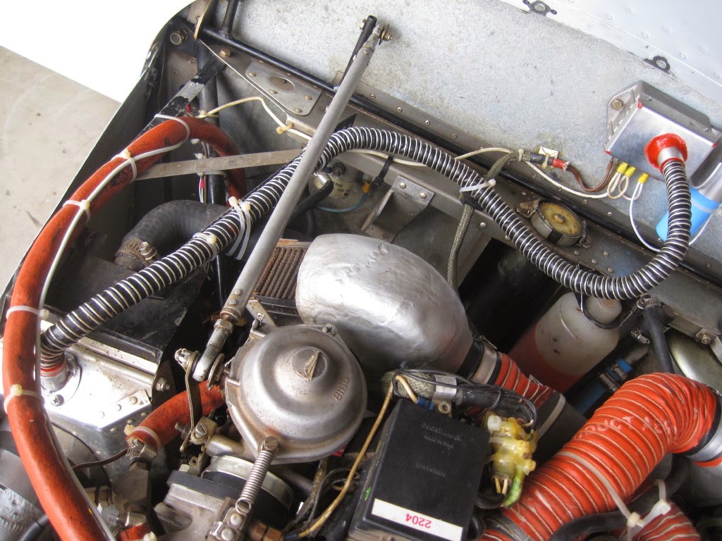
Right Choice: Propeller Blast for Cooling
We decided to use the propeller blast instead of ram air. This could be readily done by tapping into the shroud of the water radiator.
The photo above shows the complete installation.
Here are additional details.
 |
| Water radiator with blast tube |
 |
| Detail of blast tube attachment |
 |
| Angled opening of blast tube |
Evaluation of the installation was done in 101 deg F ambient air.
While taxiing, the temperature of the voltage regulator rose very slowly due to the cooling air supplied by the propeller.
After 5 min, the temperature reached 121 deg F, which gives a rate of 4 deg F/min. Assuming that rate for 10 min of taxiing, the resulting temperature would be 141 deg F.
Even 15 min of taxiing would produce just 161 deg F, a reassuring thought.
The temperature dropped immediately after takeoff and bottomed out at 106 deg F with 85 deg F ambient air at 2,500 ft MSL.
Upon landing, the temperature peaked at 145 deg F during taxi to the hangar, and after shutdown quickly dropped.
During taxiing and test flight, water temperature of the engine was always in the normal range.
Evidently, the cooling capacity of the water radiator on the ground or in the air is not affected by addition of the blast tube to the radiator shroud.
Conclusion
Installation of a cooling shroud for the voltage regulator has produced a significant reduction of the operating temperature of the voltage regulator, a pleasing result.
How Much Does the Cooling Shroud Help?
Plainly speaking, we don't know. Below are the failure data for our engine. They cover 25 years and 2,000 hrs of operation, with the engine still going strong without any sign of wear.
The original voltage regulator failed after 1,331 hrs.
The cooling shroud was installed on the second voltage regulator after 289 hrs of use.
The second voltage regulator then failed after an additional 370 hrs, and thus lasted a total of 659 hrs.
Given these numbers, one might venture the guess that the cooling shroud isn't really helping.
But that argument ignores that the performance of the voltage regulator varies greatly, and times between failure can be very short.
Just google "failure performance of Rotax voltage regulator" to see a number of posts complaining about very poor performance of the voltage regulator, including reports of failure after as little as 300 hrs.
A common theme of the posts is the recommendation that one should always carry a spare voltage regulator on all cross-country trips.
It is indeed a good very idea. You may also want to bring along a AC/DC Volt and Ohm multimeter to verify the failure, as recommended above.


HI,
ReplyDeleteInteresting research.
Could you please disclose your power consumption (Amps) during taxiing.
Thanks for a reply.
Regards,
Martin
I do not know power consumption while taxiing since the plane does not have an amp meter. But the load is high enough that the low engine rpm during taxiing make it impossible for the alternator to produce the desired voltage of 13.6 V. Indeed, the voltmeter shows around 12 V, and the electric gyro and horizon barely hide the red flags. But as soon as engine rpm goes up, say past 3000 rpm, the alternator easily handles the load.
DeleteKlaus,
ReplyDeleteVielen dank! Mit freundlichen Gruesse, Mart Bosma