Electric Fuel Pump System for Rotax 912
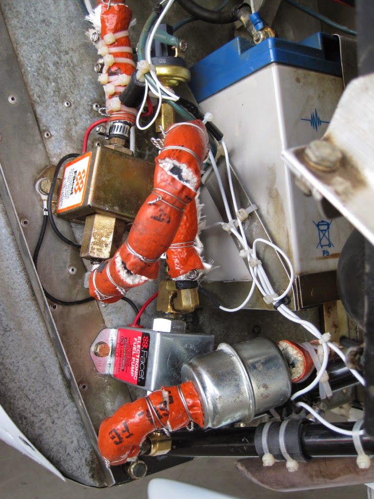 |
| Pump System with two Facet pumps and low-pressure switch |
Failures of the Mechanical Pump
Five pump failures within 1,618 hrs is astonishingly bad performance, given that mechanical diaphragm pumps, for example in Continental or Lycoming engines, generally last beyond engine TBO without a hiccup.
The pump failures were of two types.
Either the fuel pressure would drop to zero, in some cases rapidly, in others very slowly.
Or the pump would leak blue-colored oil, indicating a diaphragm failure where blue avgas was mixed with oil. That mixture would exit the cowl in front and eventually streak onto the canopy.
The shortest time between failures was 61 hrs, and the longest 729 hrs.
Rotax then offered a pump of different design. It has a vent tube where a hose is to be attached for removal of oil that may be vented by the pump.
Service Bulletin SB-912-063R1 specifies that the amount of vented oil may not exceed 0.5 ml for a 20 min engine run, or 1.5 ml per hour. The amount per hour roughly fills a cube with side length 7/16 in.
That's a lot of oil when allowed to vent overboard. Worse yet, how is the pilot to determine whether the vented amount exceeds the specified limit?
Given this troublesome feature and the dismal record of prior pumps, we decided to eliminate the mechanical fuel pump and install an all-electric fuel pump system.
This is not a new idea.
A number of homebuilt aircraft rely solely on electric fuel pumps when installation of a mechanical pump is difficult or impractical.
The system has dual fuel pumps where one pump is on stand-by and automatically starts up if the primary pump fails. Details are described below.
Given that each of the pumps can be expected to run for a long time — just search the Internet using "Facet fuel pump reliability" — the system is very reliable.
By 2019, the system has run for about 350 hrs without any hiccup. In fact, the engine has completed a total of 1,950 hrs without ever have been opened, beyond replacement of the Belleville washers of the gearbox.
Installation Details
First, the failed mechanical pump is removed and replaced by a flat plate that seals off the opening of the gear box.
 |
| Plate sealing off gearbox opening |
Note that the pumps are mounted at an angle, as recommended by the Facet installation instructions.
The primary pump has rated pressure output in the range 3.0-4.5 psi.
That rating applies only to the case when pumped volume is zero. When volume is nonzero, the pressure goes down.
For the primary pump, pressure with zero volume is about 4.2 psi. With volume 4.0 gal/hr in cruise, pressure drops to 3.2 psi.
We do not know the pressure rating for the secondary pump since it was bought almost 20 years ago for the original installation as boost pump for the mechanical pump.
The pressure by the secondary pump with zero volume is 4.5 psi. With 4.0 gal/hr, it is 3.5 psi. We estimate that the pump has run for less than 150 hrs and thus cannot have suffered any significant wear.
Fuel Flow
The flow of fuel through the pump system is as follows.
The fuel of the center tank of the plane first goes through a filter with metal housing, shown at the bottom of the photo.
Then it flows into the bottom pump, which is the primary pump.
The output of the primary pump flows to the upper, secondary pump.
Finally, the output of the secondary pump goes to the carburetors.
A pressure switch in the upper right part of the photo senses the pressure of the primary pump output.
The switch has been adjusted to achieve the following performance.
If the pressure is above a certain value P — we see later how this value is determined — the switch is open, the secondary pump does not run, and the fuel simply passes through the secondary pump to the carburetors.
On the other hand, if the primary pump pressure is less than P, the pressure switch is closed and thus turns on the secondary pump.
As a result, that pump boosts the pressure by 3.5 psi, and the fuel flows with the resulting pressure to the carburetors.
At the same time, the closed low pressure switch turns on a warning light in the cockpit that announces failure of the primary pump.
 |
| Warning light for primary pump failure |
The odds of the secondary pump also failing is exceedingly small since that pump normally runs only for a short time during each start-up and then is turned off by the pressure switch.
That step is part of the engine start-up described next.
Engine Start Procedure
When the master switch and then the pump system are turned on, the pressure switch senses zero pressure, the warning light of the primary pump comes on, and both pumps are powered.
One can clearly hear both pumps running by their clicking sounds, so there is also an audio check that both pumps are operating.
As soon as the primary pump achieves more than the critical pressure P, the pressure switch opens, and thus both the secondary pump and the warning light are turned off.
This is confirmed by reduced clicking coming just from the primary pump.
Before we discuss determination of the critical pressure value P, let's look at possible failure modes.
Failure of Alternator/Voltage Regulator
The alternator of the engine is very reliable, and the only concern is the voltage regulator. The latter equipment may fail if exposed to excessive heat.
Measurements done some time ago indicate that temperature under the cowl may be quite high, though well within the spec of the voltage regulator.
To avoid high temperatures, we have installed the cooling shroud for the voltage regulator designed by Van's Aircraft. This boosts reliability of the electrical charging system.
The battery has 28 Ah capacity. Suppose all electrical loads are turned off except for engine instruments and the GDL 39. We assume that the GDL 39 is retained since it may be crucial for navigation and weather analysis.
If the battery is fully charged, which corresponds to 12.5 V, then 10 hours of reliable power supply are available.
The panel of the plane has been placarded to provide that information, together with additional data for reduced voltage values down to 11.0 V. That lowest value suffices for the pumps. Details of this label are discussed later.
We have also replaced the hard-to-read analog voltmeter by a digital one. It flashes if the value is at most 12.0 V and thus warns the pilot about a major electrical charging problem.
The value 12.0 results from a compromise.
First, if 12.0 V is reached and electrical load is reduced as described, endurance is 5 hrs; thus, there is plenty of time to reach an airport.
Second, the threshold of 12.0 is low enough that it is not reached during engine start and taxiing with low rpm when the alternator cannot handle the electrical load.
 |
| Placard and digital voltmeter |
The Facet pumps selected for the installation have no shut-down valves. This is important since it reduces the odds of pump failure.
An attractive byproduct is the fact that, upon shutdown, fuel pressure goes to zero, thus unloading the pressure on the carburetors as fuel tubing heats up and potentially creates excessive fuel pressure.
That happened previously due to the check valve of the mechanical fuel pump.
If the primary pump fails, then the pressure switch activates the secondary pump. The latter pump is tested on each engine start, but is not used otherwise.
Hence, the secondary pump very likely will work when needed.
Pressure Switch
There are two types of failures of the pressure switch.
Failure 1: The switch does not close the circuit when pressure is low.
During each engine start it is tested that the switch closes under low pressure. So very likely the switch will do so in flight.
Failure 2: The switch does not open the circuit when pressure is high.
As a result, both pumps are running. If this happens during engine start, the problem must be investigated and resolved.
In flight, the primary pump produces 3.2 psi, and the secondary pump 3.5 psi.
Since Facet pumps have output pressure equal to input pressure plus pump pressure, in our case total pressure will not exceed 3.2 + 3.5 = 6.7 psi, which is higher than the 5.8 psi max pressure stated in the original handbook.
But the newest mechanical Rotax pump outputs 7.26 psi, so it is reasonable to assume that a pressure of 6.7 psi is acceptable.
A test confirmed that the carburetor float needles indeed shut off fuel flow under that pressure.
The additional current required by the secondary pump is just 1.0 A, so that demand is readily handled.
Determining the Critical Pressure Value P
We spent quite some time hunting for the correct pressure threshold value P.
That value is not easily determined since the facet pump does not put out even pressure.
There is a high pressure when the plunger pumps, and a low pressure when the plunger returns.
The gauge in the cockpit, indeed any typical engine gauge, does not show these fluctuations, but only the high value.
However, the pressure switch also senses the low value and triggers the secondary pump if that low value is less than the critical value P.
The latter case manifests itself by flickering of the LED indicator light in the cockpit for the secondary pump, meaning that the pressure switch cycles rapidly.
But how can we get a reading on the low pressure value, given that any engine pressure gauge only indicates the high value? It seems impossible to solve this problem using customary engine gauges.
We tried several alternate approaches, none of them satisfactory.
But then we had the right idea.
We do not depend on any direct pressure measurements, but employ an indirect method as follows.
Step 1: On the ground, with the engine not running, we turn on the primary pump.
Gradually we increase the setting of the pressure switch until the warning light begins to flicker. Thus, the secondary pump is about to be activated.
Step 2: We reduce the setting of the pressure switch by 1.5 psi.
For the pressure switch used in our installation, this is achieved by three full turns of the adjustment screw.
With that setting, the secondary switch only closes when the pressure drops to an unusually low value.
One may argue that Step 1 relies on measurement where the low pressure is determined when no fuel is pumped at all and thus does not correspond the case where fuel is actually pumped.
It turns out that, contrary to the data published for the electric pumps, we have seen that the fuel pressure varies much less with volume than claimed.
Another argument is, "Why don't you simply install a manual switch to activate the secondary pump as needed?"
A point well taken, so you may decide to implement that choice.
But our foremost concern is that a failure of the primary pump may occur — indeed according to Murphy's Law will occur — when we are distracted by another problem and will not notice a vanishing fuel pressure.
That's when the ever vigilant pressure switch will prove its worth.
Mandatory Labels
When you switch to the all-electric fuel pump system, it is mandatory that you add labels to the panel that guide the pilot.
Mind you, the system may seem so clear to you that no label seems necessary. But time erodes knowledge, so you must have labels that clearly state how the engine is to be operated and what is to be done in case of alternator failure.
Besides the early shown label of the warning light for failure of the primary pump, we have added two labels to the panel for that purpose. One tells which switches must be turned on when the engine is running.
 |
| Mandatory label for running engine |
The latter value — the endurance — depends on the battery voltage as displayed by the voltage meter. You compute the endurance, in hours, by dividing the battery capacity, in AmpHrs, for a given voltage by the total current, in Amps.
You can find the battery capacity for various voltages and the current consumption values for your installation on the Internet.
We do not anticipate that we will ever see a failure of the electric charging system, considering the extraordinary reliability of the Rotax alternator and the high reliability of the voltage regulator when it is properly cooled.
 |
| Mandatory label for endurance |
We have developed a method to make these and other labels, even in color, that does not use special equipment and costs just a few cents per label.
Conclusion
It seems to us that the system is safer than the prior combination of mechanical and electrical pump, for four reasons.
First, there cannot be an oil leak problem.
Second, Facet pumps are extraordinarily reliable.
Third, two such pumps are used in tandem where the secondary pump normally is on stand-by and is triggered by a pressure switch if the primary pump fails.
Fourth, the current consumption of the pump system is so small that even when the alternator fails, the battery charge allows the fuel pump to run for a number of hours. Just check the above label telling the endurance for that case.
Have any questions or feedback about the electric fuel pump system? Please share your thoughts in the comments.


Hi. Where can I buy 2.2psi pressure switch? Regards Michael
ReplyDeleteWe used the switch kit offered by jegs.com, item# 555-41373, cost currently $40. The kit contains the switch, adjustable from 0.5 to 24 PSI; brass T fitting; cables; and a warning light. I used a much smaller light, matching the lights already in the cockpit for normal pump operations. If the light flickers occasionally in normal operation, reduce the pressure setting a bit, but stay well above 1 PSI. The flicker results from pressure variations produced by the primary pump. As of today (May 2016), we have used the system for 150 hrs without any problem whatsoever.
DeleteYou may want to read the addendum of the post of July 2016. It describes that we have lowered the threshold for the pressure switch from 2.2 to 1.0 psi. The switch kit described above can be adjusted to that lower value. We have done so, and all works well.
Deletehaving 5 failed fuel pumps is most likely the fault of a pitted gearset. Have your gearbox inspected or, as a test, have your prop balanced; if the guy doing your prop balance tells you it will not balance ten it is for sure pitting that is shooting harmonics through the roof. Replace the gearset and all the other worn gearbox parts and the mech pump will be OK.
ReplyDeleteThe pump failures were distributed at irregular intervals over 18 years. It seems so unlikely that the gears were pitted during the early years when the first failures occurred. The Sensenich propeller is extraordinarily smooth and vibration-free. In fact, the entire engine runs without vibration throughout the entire rpm range. Friend Philip tells of some rapid pump failures even by the most recent pumps. Of course, this is anecdotal information, but leads me to believe that Rotax still hasn't solved the problem. I will stick with the all-electric fuel system and will not start a repair process to solve a problem that doesn't exist. Except for the fuel pump problem, the Rotax engine has delivered perfect performance, having run 1,750 hrs over a 20-year period, with no sign of aging.
DeleteThis sounds like a reliable and effective solution for fuel delivery.
ReplyDeleteAgree. During the past nine years of operation, not a single problem or difficulty. No wonder, really. The facet pump is as simple and reliable as one could imagine. That leaves the potential problem of a electrical system failure. We replace the battery each year as a precaution.
Delete